 English
 Français
The Latest: 155 VDC FET-driven "H-Bridge" Medium-Voltage Reclosers and Controls
Reclosers are a bread-and-butter device for distribution utilities everywhere. Traditional, separate trip and close coils were the norm for the better part of the 20th century. These coils were often actuated with very low voltage DC (<50 VDC) or standard 120 VAC. These coils were replaced by trip and close input sensing logic boards sometime around the turn of the century. Unfortunately in field application, these "sensing boards" did not perform to expectations, resulting in various operability and reliability issues.
In their latest iteration, many modern medium-voltage reclosers now utilize paired bi-directional (half-bridge) FET-driven trip and close circuits. Not only have the reclosers changed, but the controllers that drive them have changed as well.
While openly available industry information regarding the latest design iteration is scarce as always, the IEEE "RODE" (Reclosers and Other Distribution Equipment) subcommittee has met several times to discuss current offerings from manufacturers: https://ewh.ieee.org/soc/pes/switchgear/minutes/2019-2/F19RODEa6REV0.pdf
The working committee makes mention of five different models that utilize "6-wire H-Bridge trip/close" circuitry, including:
- ABB 24-pin interface at 53 VDC
- 32-pin G&W Et Al. interface at 155 VDC
- 37-pin Eaton interface at 155 VDC
- 40-pin Siemens interface at 155 VDC
- 42-pin G&W interface at 155 VDC
G&W Viper-ST and SEL-651R-2
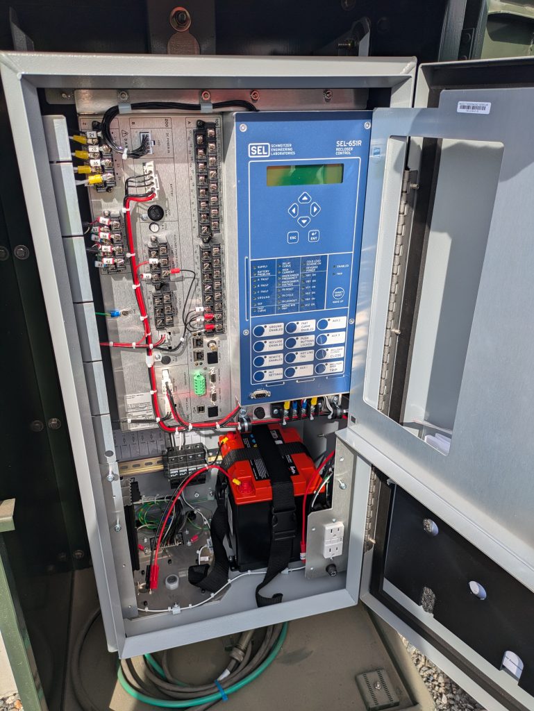
There are a variety of manufacturers, and a variety of voltages and trip and close circuit configurations, but one such pair we can study further and specifically is the G&W Viper-ST triple-single recloser and the SEL-651R-2 control. And do note the -2 designator of this control.
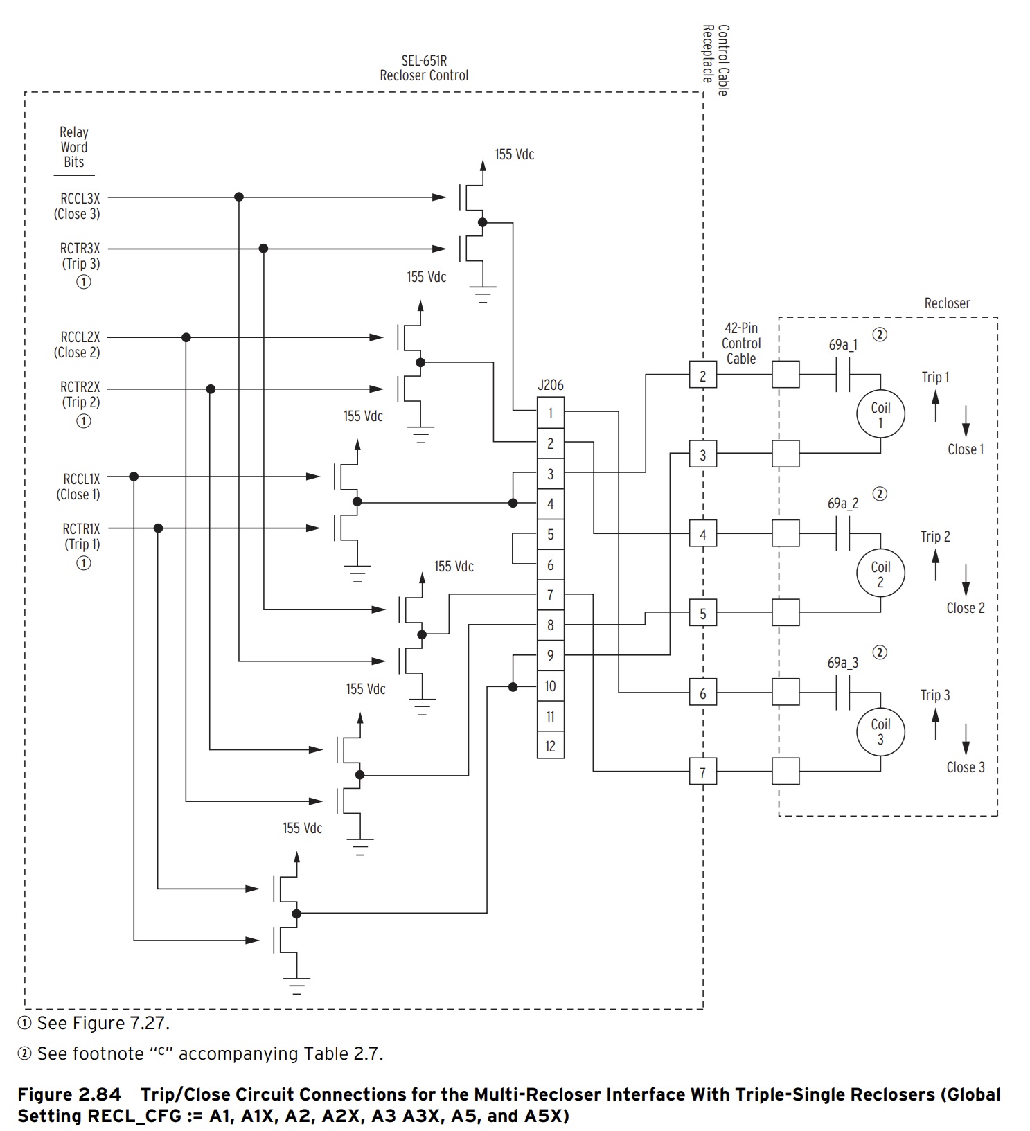
The traditional individual trip and close coils are replaced with a bi-directional "Actuator Coil". It is a Thomson coil; is it something else? Only the manufacturers know. A pair of FET's within the SEL-651R-2 relay can switch on and off to drive the Actuator Coil in the forward or reverse direction which in turn actuates the interrupter to either trip or close.
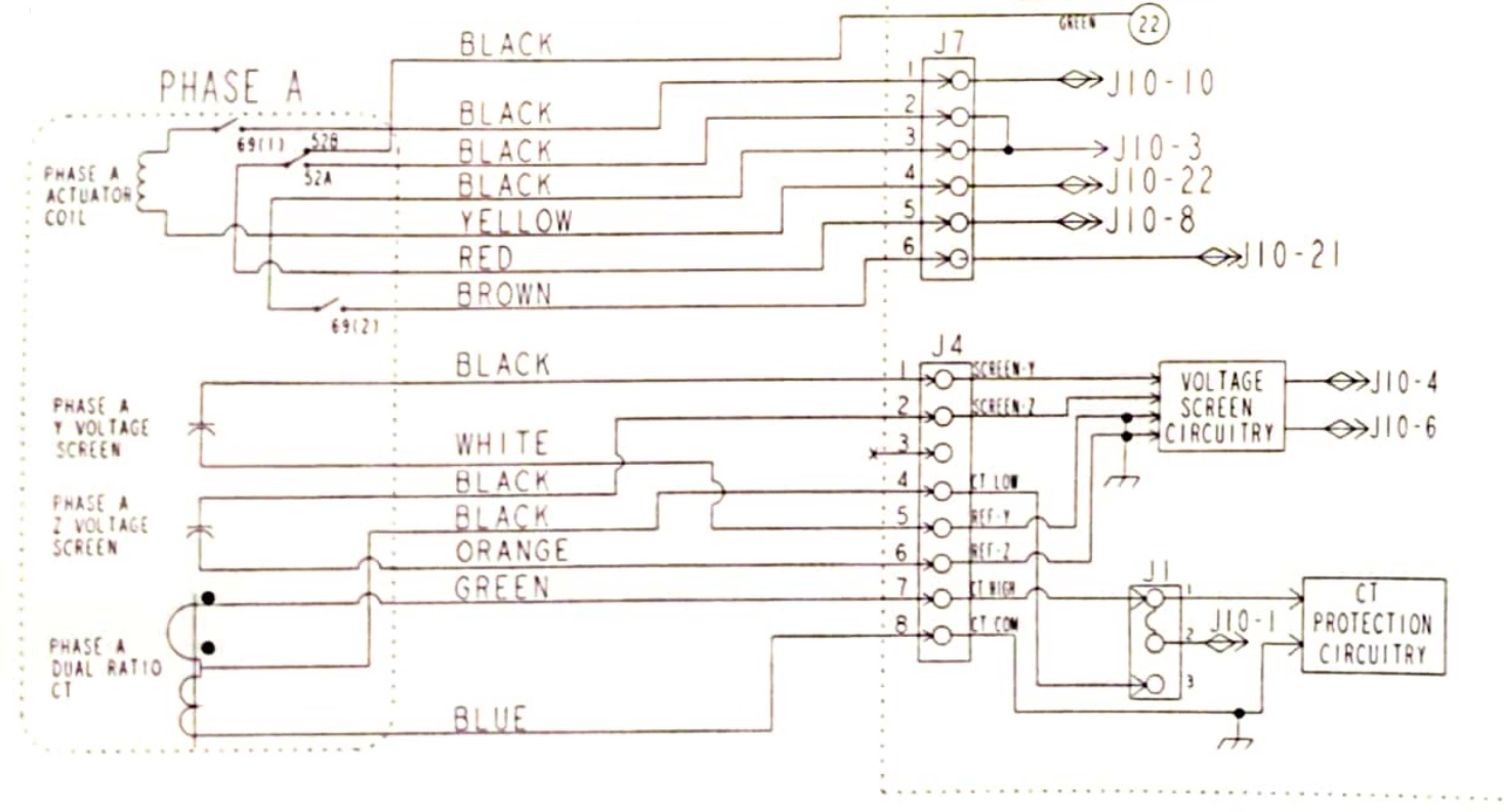
In example, the A-phase CT and control circuits of the G&W Viper-ST with LEA voltage sensors:
An SEL-651R-2 control circuit per Figure 2.84 of the controller manual:
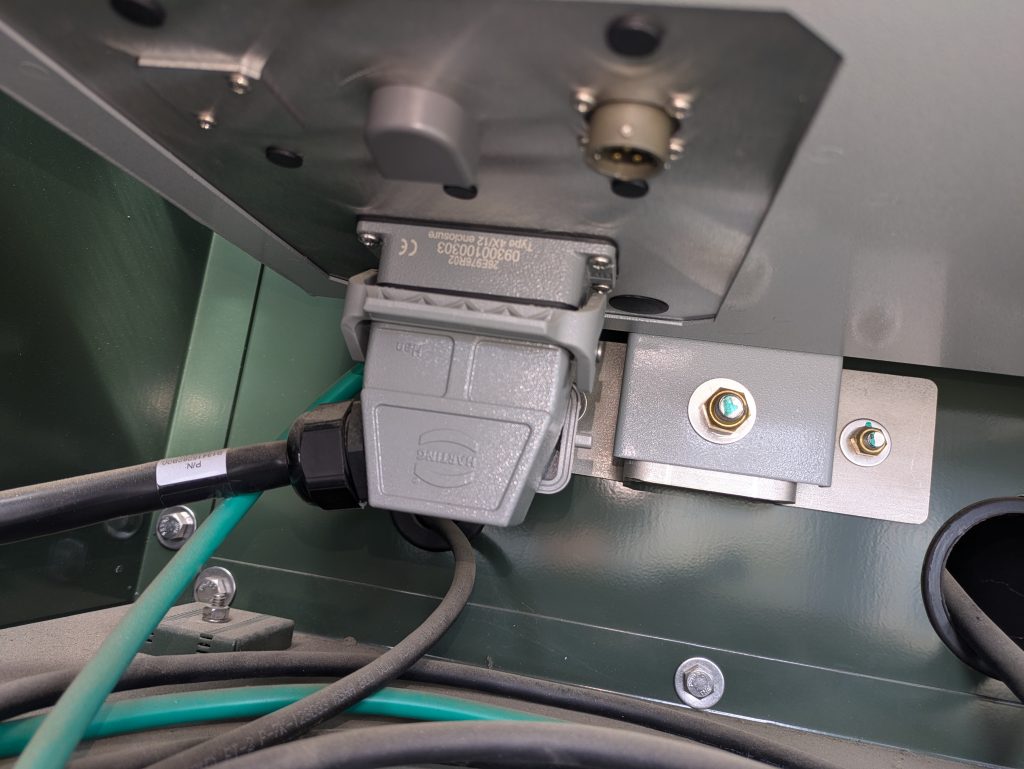
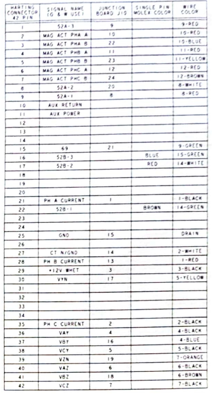
The pin-out of the 42-PIN G&W Viper-ST with dual line/load LEA voltages option:
Why do we care? The market for new special test interface cables
Your traditional recloser controls, which are typically designed to complete your trip and close circuits separately with low-voltage (<50 VDC) shock-hazard "friendly" DC or standard 120 VAC, are no longer compatible with the latest FET reclosers. And in fact, neither are your existing reclosing relay test interfaces.
Whether your brand of preference in relay testing is Omicron, Doble, or others, you may need to invest in additional test interface gear in order to interface the logic inputs and outputs of your favorite relay tester with the latest FET-driven recloser controls.
Omicron's later generation ARCO 400 already includes the necessary interface for 42-pin controls; whereas aging test sets such as the Doble F6150 will require a new and pricey test interface cables - a separate cable for each manufacturer of course - such as the F5851-42 (https://www.doble.com/wp-content/uploads/F5851-4-page-brochure-v032024-Edit2_web-1.pdf). Can you make your own cable for less money? Yes, and no. The F5851-42 cable includes "active circuitry" which converts the +-155 VDC FET signals into a lower voltage signal that is compatible with the 15 VDC threshold sending inputs of the F6150.
Alternately you may attempt to work out some sort of a deal for third-party interface equipment with small providers such as JR Test USA (https://www.jrtestusa.com/product-page/multi-recloser-interface) . We make no endorsement of and we are in no way affiliated with JR Test; they were found randomly on the internet while searching for alternatives to factory-provided interface cables.
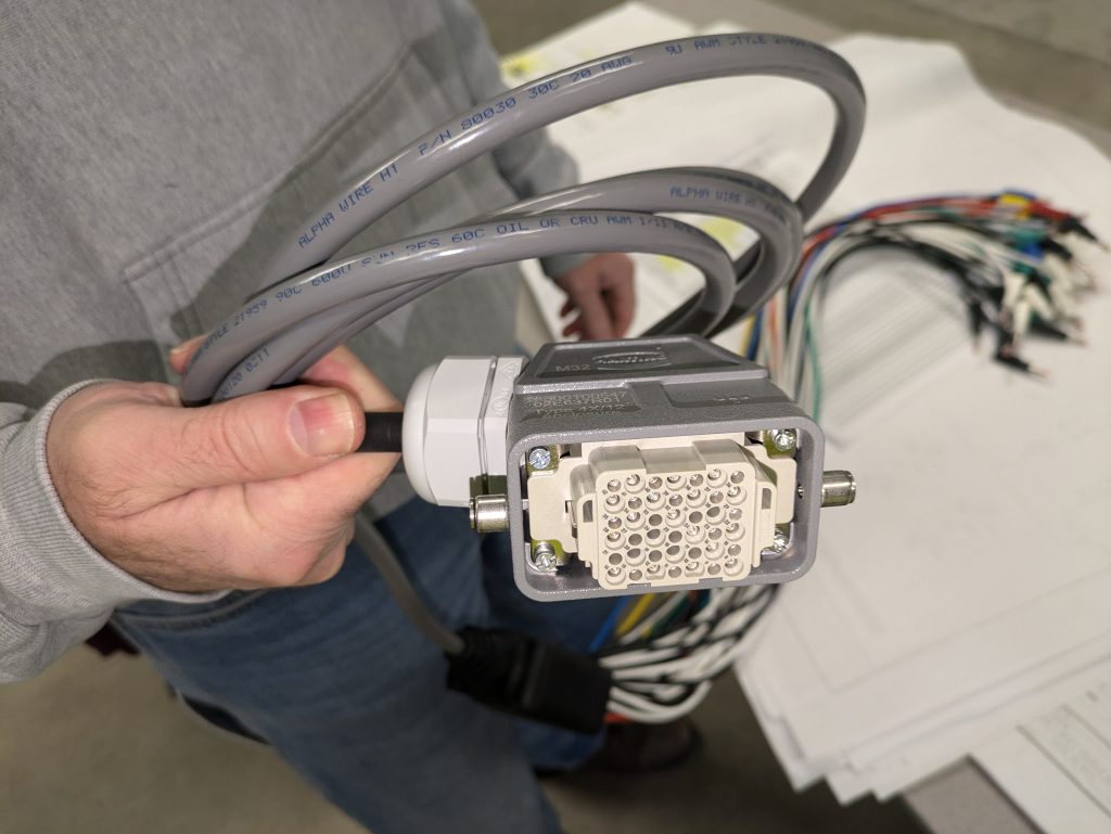
If you build your own cable, you'll have to design and test your own active circuitry and can expect no help from the manufacturers in doing so. If you do insist on attempting to build your own cable, here are 42-pin connector part numbers you might consider. Please note that one version of the connector does not have a high insertion rating and therefore is not appropriate for repeated use in this application as a test interface cable. If making your own cable, verify that crimps, connectors, and housings are rated for the appropriate application:
- Harting 09300160540 (Housing)
- Harting 09160423101 (Connector)
- Harting 09162423101 (Connector)
- Harting 01950006202 (Insert crimps)
In Conclusion
Medium-voltage reclosers, along with all industry technology, continues to evolve faster than individual contributors can keep up - at a time when openly available manufacturer information is as scarce as ever. There is still plenty of room left for learning about the new interface.
- Does the FET half-bridge drive a Thomson coil or another scheme?
- What is causing manufacturers to want to relocate trip and close circuitry from within the recloser itself to outside the recloser at the separated external controller?
- Why is 155 VDC currently the most common?
- Will the new predominant design perform better than its predecessor?
- What happened to the SEL-651R-1 controller?
It sometimes takes a concerted interest from the end-user community to drive manufacturers to provide answers. Feel free to contribute to the discussion with your colleagues and in your usual technical forums.